The wave nature of light
In geometric optics, we modeled light as rays. By considering light as rays, we could explain reflection, refraction and image formation in mirrors and lenses. But there are optical phenomena that we cannot explain just by considering light as rays. Now we consider light as waves. With the wave model of light we can understand the following optical phenomena: diffraction, interference and polarization.Wave model- Huygens' principle
If we consider a point source of light, the light spread out in all directions from the source. If we consider, the light as waves, then Christiaan Huygens, a Dutch physicist developed a wave theory of light in 1678, which is called the Huygen's principle. It states that "every point on a wave front is a source of secondary spherical waves that spread out from that point in the forward direction. The new wave front is now the envelope of the secondary waves that is tangent to those waves". A Wave front is all the points on a wave that form a wave crest. With the Huygens' principle, we can predict the future position of a wave from an earlier position.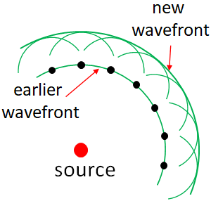
Diffraction and wave model of light
When light encounters an obstacle in its path, the light waves bend around the corners of the obstacle. This bending of waves around an obstacle is called diffraction. This happens not only for light, all types of waves, such as water waves and sound waves can undergo diffraction. With the Huygen's principle (wave model of light) we can explain the diffraction of light.Speed and wavelength change of light in a medium
By using the wave model, we can prove that when light travels from one medium to another, its speed and the wavelength changes but the frequency does not change.Speed of light, v in a medium of refractive index, n is
$v=c/n$
And, the wavelength of light, λn in the medium is
$\lambda_n=\lambda/n$
where $\lambda$ is the wavelength of light in vacuum.
Note that the frequency of light is the same whether it travels in vacuum or in another medium.Interference
Interference is a phenomenon in which two waves overlap in space and time and form a resultant wave. The amplitude of the resultant wave depends on the phase difference between the two waves. If the crest of one wave overlaps with the crest of another wave, we say that they are in-phase. But the crest of one wave overlaps with the trough of another wave, we say that they are out of phase. When two in-phase waves overlap, the amplitude of the resultant wave is the sum of the amplitudes of the two waves. This is called constructive interference.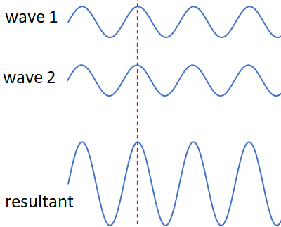
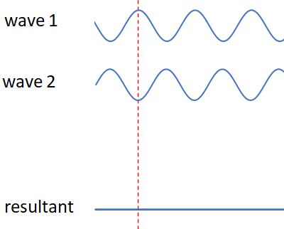
When two out of phase waves overlap, the amplitude of the resultant wave is the difference between the amplitudes of the two waves. This is called destructive interference. So, when two waves of same amplitude interfere destructively, the resultant amplitude is zero, i.e., the waves canceled out.
When two waves of same wavelength start at two different points and arrive at a same point, then constructive interference occurs if their path difference is either zero or an integer multiple of the wavelength. Path difference is the difference between the travel distance of the two waves. So, the condition for constructive interference is,
path difference $= m\lambda$, where $m=0, 1, 2, 3, ....$
If the path difference is half the wavelength or an odd integer multiple of half the wavelength, then destructive interference occurs. So, for destructive interference,path difference $= (m+1)\dfrac{\lambda}{2}$, where $m=0, 1, 2, 3, ....$
Young's double slit experiment
The first convincing experimental evidence for the wave nature of light was revealed by Thomas Young in 1801. Young performed an experiment with two slits, famously called Young's double slit experiment. With the double slit experiment, he was able to measure the wavelength of light for the first time.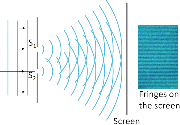
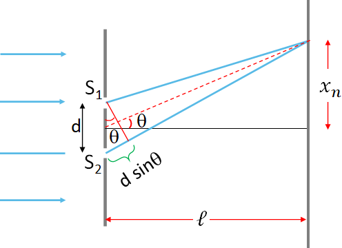
Since at the bright fringe region, the waves arrive in-phase, path difference should be an integer multiple of the wavelength, λ. So, the condition for constructive interference or bright fringes is
$d \sin\theta=m\lambda$
where $d$ is the distance between the slits and $m= 0, 1, 2, 3, ...$ is the order of the bright interference fringe.$m=0$ actually corresponds to the central bright fringe.
There are fringes on either side of the center fringe. $m=1$ means, first order fringe, there are two first order fringes on either side of the central fringe, $m=2$, the second order and so on.
At the darker regions, the waves from S1 and S2 are out of phase, and interfere destructively. Therefore, condition for dark fringes is
$d \sin\theta = (m+1)\dfrac{\lambda}{2}$
$m= 0, 1, 2, 3, ...$ is the order of the dark interference fringe. i.e., first dark fringe at $m = 0$, 2nd at $m=1$ and so on.
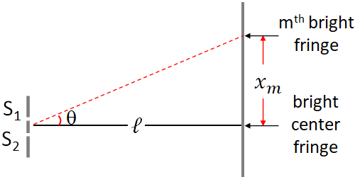
All the fringes are equally spaced. From the geometry of the above figure, we can find the distance of the mth bright fringe, $x_m$ from the central fringe. Taking the tangent of θ at the right angled triangle:
$\tan\theta=\dfrac{x_m}{\ell}$
where $\ell$ is the distance of the screen from the slits.When comparing the distance $x_n$, the screen distance, $\ell$ is very large, which makes the angle $\theta$ small so that we can take $\tan\theta=\theta$, and $\theta=\sin\theta$, so we have
$\sin\theta=\dfrac{x_m}{\ell}$
Multiplying $d$ on both sides,$d\sin\theta=d\dfrac{x_m}{\ell}$
Substituting $d\sin\theta=m\lambda$, and solving for $x_m$
$x_m=m\dfrac{d\lambda}{\ell}$
Diffraction by a single slit
Diffraction pattern (interference pattern) also occurs, when a narrow slit or a disk is illuminated with a monochromatic light. This diffraction pattern is due to the spreading of the waves (diffraction) at the slit and the interference of the waves coming from different parts of the slit.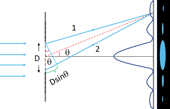
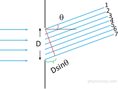
To find the condition for the constructive or the destructive interference, let us take some sample of rays (I took 7 rays) that travel at an angle, θ from the horizontal and interfere on the screen at a point corresponding to that angle. Ray 1 is from the top most of the slit and ray 7 is from the bottom of the slit. Now if you assume that the path difference between these two rays (1 and 7) is equal to the wavelength, λ, then the path difference between these two rays and the central ray (ray 4) will be λ/2 as it is in the midway. So they interfere destructively. Further, the sets, rays 2 & 5, and the rays 3 & 6 are equally spaced as of ray 1 and 4, so they also interfere destructively separately. As a result, there is only a destructive interference or a minimum occurs at D sinθ=λ. We can extend this argument to integer number of wavelengths.
So, there is minima occur at the following condition
$D\sin\theta=m\lambda$
where $m=\pm 1, \pm 2, \pm 3, ...$ is the order of the minimum (dark region), $+$ sign corresponds to one side of the central maximum and the $-$ sign, the other side.
The above equation is the condition for the minimum intensity or the dark region. In between the darker regions, there are brighter regions. The diameter of the central spot is actually the distance between the two first order minimum (darker regions).Visible light and dispersion
Color and brightness are the two main properties of light. Brightness is related to the intensity of the light and color is related to the wavelength or frequency. Wavelength of the visible light is in the range: 400 nm to 700 nm. It corresponds to a frequency range of 7.5x10¹⁴Hz to 4x10¹⁴Hz.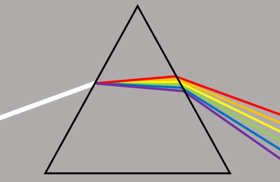
When white light is sent into a prism, it separates the light into a spectrum of colors. This is because index of refraction of a material depends upon the wavelength of the light. So, different colors (wavelengths) refract at different angles by the prism. The spreading of white light into a spectrum of colors is called dispersion. Rainbow is the result of dispersion by water molecules.
Diffraction grating
In the double slit experiment, there were two slits. If we increase the number of slits, we can have sharp and narrower fringes. A large number of parallel slits, which are equally spaced is called a diffraction grating. Diffraction gratings are widely used to separate the colors of light.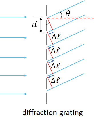
When monochromatic parallel rays of light strike a diffraction grating, the light is diffracted at the slits. If a screen is placed behind the grating, we can see interference pattern on the screen due to the interference of the light waves from the slits.
If we consider the waves from the slits, which diffract at an angle θ, we can see that between the adjacent slits, the path difference of the waves is $\Delta \ell=d \sin\theta$, where $d$ is the distance between the slits (adjacent slits). The screen distance in general is much larger than the slit separation. Therefore, all the waves at the angle θ from the horizontal, arrive at the screen at the same angle and interfere at a point corresponding to that angle.
If the path difference, $\Delta \ell$ is equal to an integer multiple of the wavelength of the light, then there is a constructive interference occurs. So, the condition for maximum brightness is
$d \sin\theta=m\lambda$
where $m=0,1,2, ... $. m is called the order of the diffraction pattern, i.e., $m=1$ is the first order, $m=2$, the second order etc.The above equation is called the grating equation.
The central line corresponds to $m=0$ is always bright. It is followed by dark and then bright regions and so on, on either side of the central line.
From the grating equation, you can find that at what angle, $\theta$ we get bright fringes.
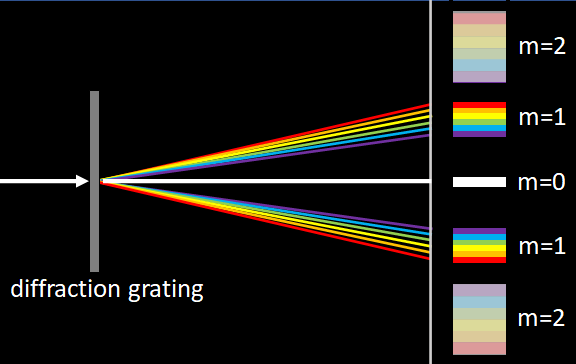
Based on the grating equation, we see that the diffraction angle depends on the wavelength of the light. So, lights of different wavelengths diffract at different angles.
Instead of a monochromatic light, if a white light is sent into a diffraction grating, in the center of the pattern we will have a sharp white line. This is because at the central spot, all the colors of the white light interfere constructively. On either side of the central line, there will be a spectrum of all the colors in different orders, where different colors interfere constructively at different angles, so there is a spread of the colors.
Interference in thin films
You might have noticed that thin films such as soap bubbles, and oil (or gasoline) films reflect bright colors. This is due to the reflection and the interference of the light waves coming from the surfaces of the thin films. All films have two surfaces, a top and a bottom surface. When light incident on the top surface, part of the light is reflected and part is transmitted into the film. Part of the transmitted light is then reflected back by the bottom surface. The reflected waves from the top and the bottom surface interfere. If the incident light is white (sunlight), then the different colors (wavelengths) interfere constructively at different angles, which results in bright colors.Phase shift upon reflection
If a beam of light, incident on a material of higher refractive index than that of the medium it is coming from, then the light reflected by the material will have a phase shift of 180°, which is equivalent to a path difference of half the wavelength.Polarization
Light is an electromagnetic wave with oscillating electric and magnetic fields. If the oscillation of the electric field is in a plane we call the light plane polarized. We consider the direction of the electric field as the direction of polarization. Light can be polarized or unpolarized. Ordinary light such as sun light and light emitted by light bulbs are unpolarized light.Polarizer
An optical element that can produce polarized light is called a polarizer. When we send light through a polarizer, it allows light to pass through in only one direction, and that direction is called the transmission axis of the polarizer. An example of a polarizer is a polaroid sheet. It consists of long complex molecules arranged parallel to one another, which allows light of one polarization direction to pass through and absorbs the rest. We use the following symbols to represent an unpolarized light and a polarized light.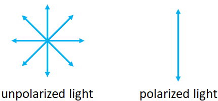
Law of Malus
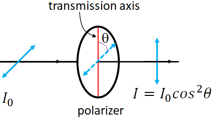
$I=I_0 \cos^2\theta$
where $\theta$ is the angle between the transmission axis of the polarizer and the direction of polarization of the light.An unpolarized light consists of light with random polarization directions, i.e., the polarization in all directions.
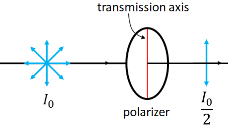
$I=I_0/2$.
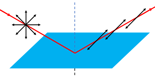
Polarization by reflection
We can also produce a polarized light by reflection at a nonmetallic surface. When light incident on a nonmetallic surface at an angle other than perpendicular, the reflected light is polarized in the direction parallel to the surface.