Geometric optics
Geometric optics is about describing the light propagation by considering light as rays. Light travels in straight lines and the paths of light are called rays. By considering (modeling) light as rays, we can successfully explain the phenomena such as reflection, refraction and formation of images by mirrors and lenses.Reflection of light
When light strikes the surface of an object, part of it is reflected. We consider light as a collection of rays and each ray travels in a straight line. In the following figure, you see the reflection of a light ray by a smooth surface. The ray of light that strikes the surface is called incident ray. The incident ray reflects at the surface, and we call that the reflected ray.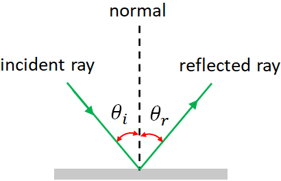
If you draw a line perpendicular to the surface at the point where the incident ray strikes the surface, we call that line, the normal. Normal is the dotted line in the figure. The angle between the incident ray and the normal is called the angle of incidence, θi. And, the angle between the reflected ray and the normal is called the angle of reflection, θr.
The law of reflection
When light reflects at a surface, the angle of incidence is always equal to the angle of reflection. i.e.,$\theta_i=\theta_r$
This is called the law of reflection.Specular and diffuse reflection
When a beam of light reflects on a smooth surface such as a mirror, it reflects into one direction. This type of reflection is called specular reflection. But when light incident on a rough surface, it is reflected into many directions, such a reflection is called diffuse reflection. Diffuse reflection help us to see an ordinary object in different angles.Plane mirror
A plane mirror is a mirror with a flat smooth reflecting surface. Light rays from an object (O) in front of the mirror are reflected at the mirror and enter the viewer's eyes. I took three rays from the object. The rays and their reflected rays based on the law of reflection are shown in the figure below. The reflected rays appear to come from a point (I) behind the mirror. And the image is formed at that point.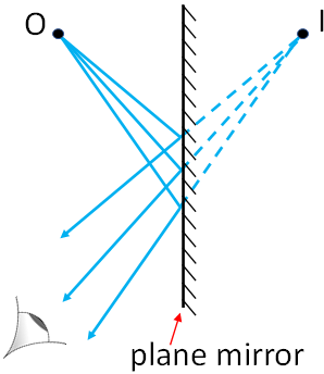
We call, the distance between the object and the mirror, the object distance, $d_o$. The distance between the image and the mirror is called the image distance.
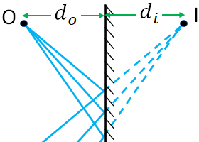
In a plane mirror, the image distance is exactly equal to the object distance. i.e.,
$d_i=d_o$
Spherical mirrors
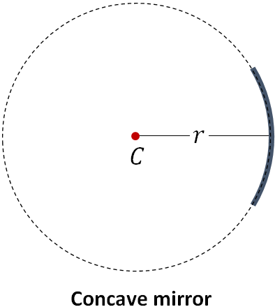
A mirror with a curved reflecting surface and the surface is a part of a spherical surface is called a spherical mirror. There are two types of spherical mirrors: concave and convex mirrors.In a concave mirror, reflection takes place at the inner surface. The center of the reflecting surface curves away from the light source. A concave mirror is also called a converging mirror.
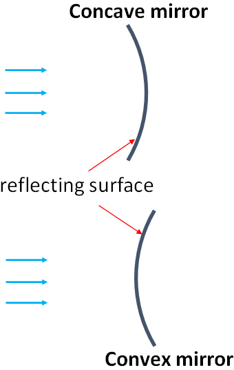
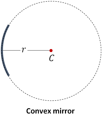
In a convex mirror, reflection takes place at the outer surface. The center of the reflecting surface bulges out toward the light source. A convex mirror is also called a diverging mirror.
Since a spherical mirror is a part of a spherical surface, we can draw a sphere out of the mirror. The center, $C$ of that sphere is called the center of curvature of the mirror. The radius, $r$ of the sphere is the radius of curvature of the mirror.
Concave mirror
When parallel rays of light incident on a concave mirror, they are reflected by the mirror and pass through a point, F. The point, F is called focus.If we draw a straight line that is perpendicular to the mirror and passes through the center of the mirror, it is called the principal axis of the mirror. By using the law of reflection, we can realize the following facts about the light rays reflected by a concave mirror.
- If a ray of light travels along the principal axis, it is reflected back along the principal axis. This is because the ray incident perpendicular to the mirror.
- The rays parallel to the principal axis are called parallel rays, which are reflected by the mirror and pass through the focus.
- If a ray passes through the focus, its reflected ray will travel parallel to the principal axis.
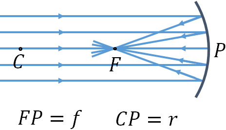
In the figure, $P$ is the center of the mirror, $C$ is its center of curvature and $r$ is the radius curvature.
The distance between the focus and the mirror is called the focal length, $f$ of the mirror.
For any spherical mirror, we get$f=r/2$
Image formation in a concave mirror
To find how the image is formed in a concave mirror, we draw the path of the light rays, called ray diagram. I consider the object as a vertical arrow. For convenient, I take the bottom of the object is on the principal axis of the mirror. In the figure, OO' is the object, the point O' is the top of the object and O is its bottom. To locate the image of the object, we need to consider at least two rays of the light coming from the top of the object. And for the bottom, we take the ray that travels along the principal axis. Since the ray travel along the principal axis reflects back into the same axis, the principal axis itself will serve as the reflected ray.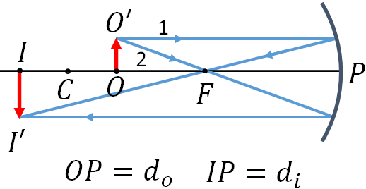
I take two rays from the top of the object, ray 1, a parallel ray and ray 2, which passes through the focus.
The ray 1 that goes out from the top of the object (O') is a parallel ray, so it reflects and then passes through F, the focus.The ray 2, goes through F, so it reflects back parallel to the principal axis of the mirror.
The reflected rays of the two rays intersect at a point I'. So the top of the image will be focused at I'. And the bottom of the image will be at I. So, the image is II', which is inverted (upside down) as the arrow points downward.
The image is formed in a real location, so, it is real. If you place a screen at the image location, you can see it on the screen.
As in plane mirrors, object distance, $d_o$ is the distance of the object from the center of the mirror and the image distance, $d_i$ is the distance between the image and the center of the mirror.
From the geometry of the above figure, we can find an equation that relates the object distance, image distance and the focal length of the mirror. Such an equation is called mirror equation.The mirror equation is
$\dfrac{1}{d_i}+\dfrac{1}{d_o}=\dfrac{1}{f}$.
Magnification, $m$ of a mirror is defined as the ratio of the height of the image to the height of the object.i.e., $m=\dfrac{h_i}{h_o}$.
From the geometry of the figure, we can show that $\dfrac{h_i}{h_o}=-\dfrac{d_i}{d_o}$, therefore,$m=\dfrac{h_i}{h_o}=-\dfrac{d_i}{d_o}$.
We will use the following sign convention that is applicable for all types of mirrors.
- $f$ and $r$ are positive for a concave mirror and negative for a convex mirror.
- The object distance, $d_o$ is always positive.
- The image distance, $d_i$ is positive if the image is in front of the mirror and is negative if it is behind the mirror.
- Image height, $h_i$ is positive if the image is upright and is negative if the image is inverted relative to the image.
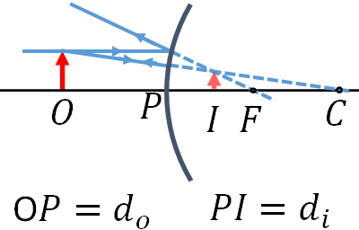
Image formation in a concave mirror: object close to the mirror
In the image formation discussed in the previous section, we placed the object before the focus, F. Now, we will see what will happen if the object is close to the mirror, i.e., the object is placed between F and the mirror. The ray diagram for such a scenario is given in the figure below.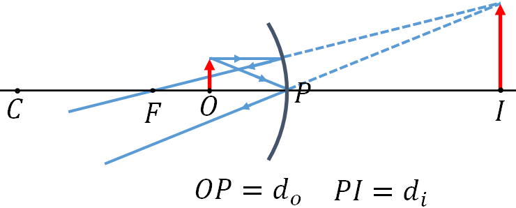
I took two rays from the top of the object. One is a parallel ray and the other is the one that incidents at the center of the mirror. Since, there is no ray that can pass through the focus and incident on the mirror, I took the second ray as the one that is incident at the mirror center.
If you look at the reflected rays of the two rays that we considered, they do not intersect at a point. But if you look opposite to the reflected rays direction, you will see that the two rays appear to come from a point behind the mirror. And at that location, the image is formed. The image appears to be behind the mirror, like the image in a plane mirror. Since there is no real light passes the image location, the image is virtual. You cannot project the image on a screen. As you see in the figure, the image is upright.
So, a concave mirror can form a real or a virtual image, depending upon the position of the object.
Convex mirror
In a convex mirror, reflection takes place at the outer surface. By applying the law of reflection, we can find that the parallel rays incident on a convex mirror diverge in front of the mirror, but they appear to come from a point behind the mirror, which you can see by extrapolating the reflected rays (dotted lines). The point, where the reflected rays appear to come from is the focus, $F$ of the mirror.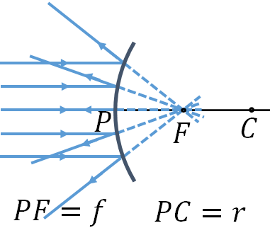
Image formation in convex mirror
Based on the sign convention, $d_i$ is negative, and therefore, magnification, $m$ is positive for a convex mirror.
Refraction of light
Speed of light and refractive index
Speed of light depends on the medium in which it propagates. In vacuum, speed of light, $c$ is$c=3\times 10^8 \,m/s$
Speed of light in air is closer to the speed of light in vacuum, so we consider the speed of light in air or in vacuum as $c$. In other media, speed of light is smaller than $c$. In a medium other than vacuum, the speed of light, $v$ is
$v=\dfrac{c}{n}$
where $n$ is called the refractive index or index of refraction of the medium.For air, $n=1$ and the refractive index of water is, $n=1.33$.
Refraction
Refraction is another optical phenomenon that takes place at an interface between two different media.When a light ray incident on an interface between two media of different refractive indices, its direction changes. This is called refraction.
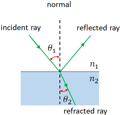
In the figure, a light ray passes from a medium of lower refractive index, n1 into another medium of higher refractive index, n2. As an example, you can consider the first medium as air ($n_1=1.00$) and the second as water ($n_2=1.33$). At the interface, some of the light is reflected and the rest passes into the second medium. The ray reflected into the first medium is called the reflected ray, which you learned in reflection. The ray transmitted into the second medium is called refracted ray. The refracted ray bends toward the normal at the interface.
We considered, $n_1\lt n_2$, where the refracted ray bend towards the normal. But if $n_1\gt n_2$, that is the light ray travels from a medium of higher refractive index into a medium of lower refractive index, for example, from water to air, then the refracted ray bends away from the normal.
Note that the light won't bend, if it incident perpendicular to the surface. i.e., if a ray of light incidents perpendicular to the surface, then the ray transmitted in the same direction in the second medium.
Law of refraction or Snell's law
The angle between the refracted ray and the normal is called the angle of refraction, θ2. The angle of refraction depends on the angle of incident, θ1, and the refractive indices of the two media. An experimental law relates θ1 and θ2 and is given by$n_1 \sin\theta_1= n_2 \sin\theta_2$
This equation is called the law of refraction and is also called Snell's law.Total internal reflection
Total internal reflection is an optical phenomenon that takes place when light travels from a medium of higher refractive index to a medium of lower refractive index.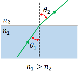
Let us consider a ray of light traveling in a medium of refractive index, $n_1$, enters another medium of refractive index $n_2$, where $n_1\gt n_2$. We start with a smaller value of the angle of incidence, $\theta_1$. The ray bends and is away from the normal as in the figure above.
Now, if you increase the angle of incidence, the angle of refraction also increases according to the Snell's law. If you keep increasing, you can notice that at one particular angle of incidence, the refracted ray would skim the boundary.
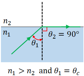
We can find the critical angle by putting $\theta_1=\theta_c$ and $\theta_2=90^\circ$ in the Snell's law:
$n_1 \sin\theta_c = n_2 \sin90$
From this, we can write,
$\sin\theta_c=\dfrac{n_2}{n_1}$
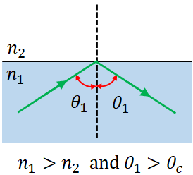
You can find the critical angle, $\theta_c$ of an interface between the two media by this equation.When the angle of incidence is greater than the critical angle, i.e., $\theta_1>\theta_c$, all the light is reflected back in to the first medium and no refracted light into the second medium. This phenomenon is called total internal reflection.
Thin lenses
Lenses are optical elements, they work based on the law of refraction. A lens is made of a transparent material, usually glass and has two curved surfaces. There are also lenses available with one curved surface and the other plane surface.There are two types of lenses: converging lens also called convex lens and diverging lens also called concave lens. A converging lens is thicker at its center than the edges. A diverging lens has its edges thicker than the center.
A thin Lens is a lens with its thickness smaller than the radii of curvature of its surfaces. In this page, our focus will be on thin lenses.
As in spherical mirrors, a perpendicular straight line passing through the center of the lens is called principal axis. And the light rays travel parallel to the principal axis are called parallel rays.
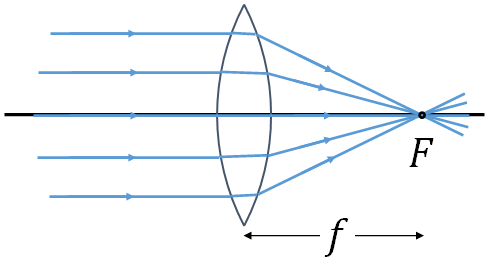
By the law of refraction, we can see that if parallel light rays fall on a converging lens, they focus on a point on the other side of the lens. The converging point is called the focal point or the focus, F of the lens.
If parallel light rays fall on a diverging lens, they diverge. These diverging rays appear to come from a point, which is the focal point of the lens.
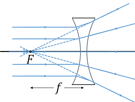
The distance between the focal point and the center of the lens is the focal length of the lens. Focal length of a converging lens is positive and that of a diverging lens is negative as you will see in the sign convention.
A converging lens is also called a positive lens and a diverging lens, a negative lens.
Converging lens- image formation
The ray diagram for a converging lens is as shown below. As in mirrors, we need at least two rays from the top of the object to locate the image of the object. I take 3 rays here (but 2 is enough). The parallel ray (ray 1) leaves from the top of the image refracts and pass through the focal point behind the lens. The ray 2, which incident at the center of the lens, pass straight through the lens as we consider the lens is thin. And the ray 3, passes through the focal point in front of the lens, which refracts parallel to the principal axis behind the lens.A real image is formed where the refracted rays intersect. As you see, the image is inverted. The object distance, $d_o$ is the distance of the object from the lens's center and the image distance, $d_i$ is the distance of the image from the lens's center.
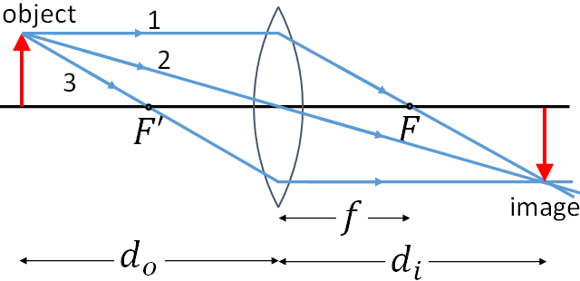
$\dfrac{1}{d_i}+\dfrac{1}{d_o}=\dfrac{1}{f}$
This is called the lens equation.Magnification, $m$ of a lens is defined as the ratio of the height of the image to the height of the object. That is
$m=\dfrac{h_i}{h_o}=-\dfrac{d_i}{d_o}$.
Note that the lens equation, and the mirror equation are the same. Magnification equation for the lenses and the mirrors are also the same. But the sign conventions are different. For lenses we will use the following sign convention:- $f$ is positive for converging lens and negative for diverging lens.
- $d_o$ is positive if the object is on the side of the lens from which the light is coming (in most cases it is positive).
- $d_i$ is positive if the image is on the opposite side of the lens where the light is coming.
- $h_i$ is positive if the image is upright, and negative if the image is inverted.
These are applicable for all types of lenses.
Converging lens - image of an object that is close to the lens
If we place an object closer to the lens, i.e., the object is between the focus and the lens, then the image will be virtual as you will see below.The ray diagram with the object closer to the lens is shown in the figure below.
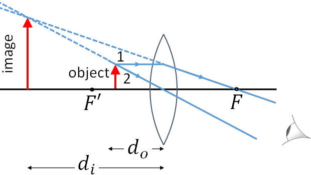
I took two rays to locate the image. A parallel ray, ray 1 and another ray, ray 2 that incidents at the center of the lens. Ray 1 refracts through the focus and the ray 2 passes straight through the lens. The refracted rays do not intersect at any point. But when we look from the position shown in the figure, the two refracted rays appear to originate from a point in front of the mirror. The image is formed in that region. You see that the image is upright and virtual as no light passes through the image location and you cannot form the image on a screen.
Diverging lens - image formation
The ray diagram for a diverging lens is shown below.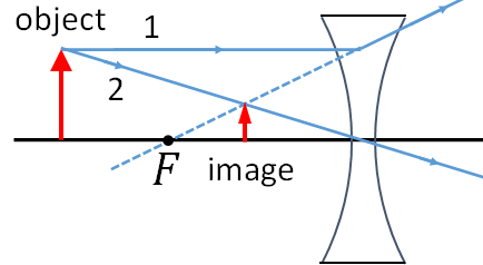
As you see in the picture, the image is virtual. Note that a diverging lens always form a virtual, upright image and the image size is always smaller than the object size.
Power of a lens
Power, P of a lens is the reciprocal of its focal length.i.e., $P=1/f$
Unit of lens power is diopter (D), which is same as $m^{-1}$.
Combination of lenses
When combining two lenses, the image of the first lens becomes the object of the second lens. The image from the second lens is the final image.Total magnification, $m$ of a two lens system will be the product of the magnifications of each lens:$m=m_1m_2$.
where $m_1$ is the magnification of the first lens and $m_2$ is that of the second lens.