Electromagnetic induction
Induced current
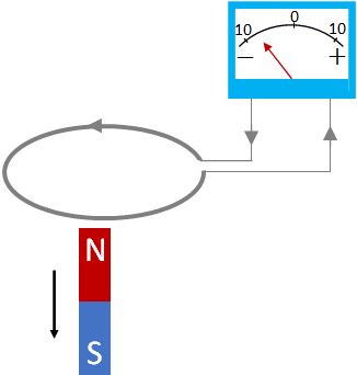
In 1831, Michael Faraday discovered electromagnetic induction. Electromagnetic induction is the production of an emf across a coil (or a conductor) by changing the magnetic field around it. Faraday found that when a magnet is moved quickly into a coil of wire, a current is induced in the coil. Further, if the magnet is moved away from the coil, current is induced in the opposite direction.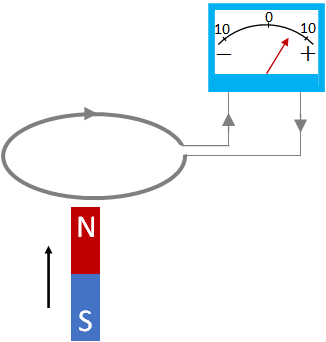
Magnetic flux and Faraday's law
Magnetic flux is related to the amount of magnetic field through an area.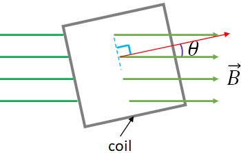
$\Phi_B=BA \cos\theta$
where $\theta$ is the angle between the magnetic field and a line drawn perpendicular to the face of the coil.When there is a change in magnetic flux through the coil, an emf is induced in the coil. The induced emf is,
$\mathcal E=-\dfrac{\Delta \Phi_B}{\Delta t}$
This is called the Faraday's law of induction.If there are $N$ loops or turns in the coil, then the emf from each loop add up assuming same flux pass through each loop, so the induced emf will be
$\mathcal E=-N\dfrac{\Delta \Phi_B}{\Delta t}$
Lenz's law and the direction of the induced current
Due to the induced emf, an induced current flows in the coil. What is the direction of the induced current?We can determine the current direction by a law, called Lenz's law.
It states that "the direction of the induced current produced by an induced emf is such that the magnetic field of the induced current opposes the change in flux that induces the current.
We have a magnetic field, $\vec B$ responsible for the induced current. Further, the induced current also produces a magnetic field. Let it be $\vec B_{ind}$. According to the Lenz's law, $\vec B_{ind}$ opposes the change in flux responsible for the induced current.
What is the direction of the change in flux?
If the emf is induced due to an increase in flux, then the direction of the change in flux is in the direction of $\vec B$. And, if the flux decreases, then the direction of the change in flux is opposite to the direction of $\vec B$.Now, you can find the direction of the current with the right hand rule for the magnetic field around a current carrying wire. The direction of the current is such that $\vec B_{ind}$ is opposite to the direction of the change in flux.
The minus sign in the Faraday's law is the result of the Lenz's law to show that the magnetic field of the induced current opposes the change in flux.
Since the induced emf is produced whenever there is a change in flux, there are many ways to induce an emf as there are many ways to change the flux. The flux can be changed by changing the magnetic field or by changing the area of the coil or by changing the angle $\theta$ (i.e., by rotating the coil).
Induced emf in a moving conductor
Another way to produce an induced emf is by increasing the area of an U shaped conductor by sliding a rod attached to it as in the figure below. In the figure, there is an U shaped conductor with a movable rod, is in a uniform magnetic field. The magnetic field is out of the page and is perpendicular to the area of the conductor.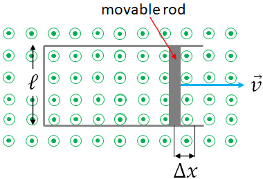
Assume the rod moves to the right with a constant speed $v$. During a time, $\Delta t$, the width of the conductor increases by an amount $\Delta x$. This increases the area of the conductor. The increase in area during the time, $\Delta t$ is
$\Delta A=\ell \Delta x$
Therefore, the change in flux through the conductor is
$\Delta \Phi_B=B\Delta A=B\ell \Delta x$
Now, you can use the Faraday's law to find the induced emf. The magnitude of the induced emf is$\mathcal E=\dfrac{\Delta \Phi_B}{\Delta t}=\dfrac{B\ell \Delta x}{\Delta t}$
On the right hand side, $\dfrac{\Delta x}{\Delta t}=v$, the speed of the rod, therefore,$\mathcal E=Blv$
Electric generators
An electric generator transforms mechanical energy into electric energy. It consists of a flat coil of wire of many turns, which is placed in a magnetic field. The coil can rotate freely.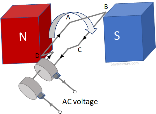
Magnetic flux is zero when the face of the coil is parallel to the magnetic field and is maximum, when the face of the coil is perpendicular to the magnetic filed. So, the magnetic flux continuously changes as the coil rotates.
Assume, initially the face of the coil is perpendicular to the magnetic field with the section AD of the coil at the bottom. At this position, the magnetic flux through the coil is at its maximum value as the face of the coil is perpendicular to the field. Now, consider the coil starts rotating in the clockwise direction. When the coil rotates, the flux decreases until it rotates by 90°. During this time interval, the current flows in the direction as shown in the figure according to the Lenz's law and the right hand rule. That is, in the section AD, the current flows from D to A, and from B to C in section BC. At 90°, the flux is zero because the field and the coil are parallel to each other. Then, from 90° to 180°, the flux increases, and the current flows in the same direction. At 180° the flux is maximum again and at this position, the section BC is at the bottom and AD is at the top. So, now BC is in the position of AD at the initial time. So, when the coil rotates from 180° to 360°, the current in the section BC is from C to B and in section in section AD, it is from A to D. It is opposite to the current direction in the first half cycle. So, in each cycle, the direction of the current changes once. If the coil makes ten full rotations, then the current direction changes ten times.
If the coil in an ac generator is spinning at an angular frequency $\omega$, then the emf induced in the generator is
$\mathcal E=NAB\omega\: \sin(\omega t)$
or$\mathcal E=\mathcal E_0\: \sin(\omega t)$
where $N$ is the number of turns in the coil, $A$ is the area of the coil and $\mathcal E_0=NAB\omega$ is the peak voltage.Transformers
A transformer is an electric device used to raise or lower an ac voltage. It consists of two coils of wires: a primary coil and a secondary coil. The two coils are linked by an iron core as shown in the figure below.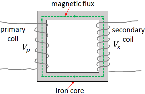
$V_s=N_s\dfrac{\Delta \Phi_B}{\Delta t}$
where $N_s$ is the number of turns in the secondary coil.In the primary coil, the applied voltage, $V_p$ changes the flux through it, therefore, we can write:
$V_p=N_p\dfrac{\Delta \Phi_B}{\Delta t}$
where $N_p$ is the number of turns in the primary coil.Dividing the above two equations:
$\dfrac{V_s}{V_p}=\dfrac{N_s}{N_p}$
From this equation, you can see that if the secondary coil has more turns than the primary coil, the voltage across the secondary coil is higher than the voltage across the primary coil and the transformer is called a step-up transformer. If the secondary coil has less number of turns than the primary coil, then voltage across the secondary coil is less than that of the primary coil, and the transformer is called a step-down transformer.Since energy is conserved, and so the power, the output power, $P_s$ at the secondary coil cannot exceed the input power, $P_p$ at the primary coil. If there is no power loss in the transformer, then, the two powers are equal:
$P_s=P_p$
Using $P=IV$, we can write,
$I_sV_s=I_pV_p$
or$\dfrac{I_s}{I_p}=\dfrac{N_p}{N_s}$
where $I_p$ and $I_s$ are the currents in the primary and the secondary coil.This equation shows that if there is more turns in the primary coil than the secondary coil, then the current in the secondary coil is larger than that of the primary coil. But you will have low voltage at the secondary coil. So, there is a trade-off between the voltage and the current. If you want a higher output current, you should live with a lower voltage and vice versa.
Transformer is a highly efficient electric device, typical power conversion efficiency of a transformer is between 98 and 99%.