DC circuits
An electric circuit that has at least one DC source such as an electric battery and no ac source is called a DC circuit.Emf and terminal voltage of a battery
The voltage measured between the terminals of a battery when nothing else is connected to the terminals is called the electromotive force or $emf$. That is, $emf$ is the open circuit potential difference measured between the terminals when no current flows to an external circuit from the battery.The voltage measured across the battery when a current flows from it to a circuit is called the terminal voltage. That is the terminal voltage is the voltage measured between the terminals when a circuit is connected to the battery.
All batteries have some resistance, called internal resistance, $r$.
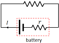
$V=\mathcal E-Ir$
where $I$ is the current flows from the battery.
In most cases, we can neglect the internal resistance of the battery, and we will have, $V=\mathcal E$.
Resistors in a circuit
Resistors are used to control current in electric circuits.Resistors in series
When two or more resistors are connected end to end as shown below, they are said to be connected in series.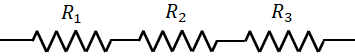
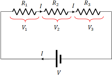
If $I$ is the current through the resistors, then the voltage across the resistors, $R_1$, $R_2$ and $R_3$ (by Ohm's law) are
$V_1=IR_1$; $V_2=IR_2$; and $V_3=IR_3$
In the circuit, the supply voltage, $V$ from the battery is split across the resistors. Therefore,
$V=V_1+V_2+V_3$
Now the question is can we replace the three resistors with a single resistor and still have the same circuit ?. The answer is yes. A resistor that replaces all the three resistors is called equivalent resistor. And the resistance of the equivalent resistor is called equivalent resistance, $(R_{eq})$.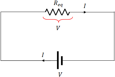
The same current, $I$ flows through the equivalent resistor. Since the equivalent resistor is connected directly across the battery, voltage across it is same as the battery voltage. So, by using Ohm's law, we can write the voltage across the equivalent resistor as,
$V=IR_{eq}$
Substituting $V$,
$V_1+V_2+V_3=IR_{eq}$
Substituting $V_1$, $V_2$ and $V_3$,
$IR_1+IR_2+IR_3=IR_{eq}$
Dividing out the $I$,$R_{eq}=R_1+R_2+R_3$
This shows that if two or more resistors are connected in series, the equivalent resistance is the sum of the resistance of the resistors.Resistors in parallel
When resistors are connected such that one end of all the resistors are together and also the other ends together, they are said to be connected in parallel.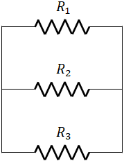
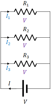
$I_1=\dfrac{V}{R_1}$; $I_2=\dfrac{V}{R_2}$; $I_3=\dfrac{V}{R_3}$
If $I$ is the supply current from the battery, then
$I=I_1+I_2+I_3$
As in the series circuit, we can replace all the resistors by a single resistor with equivalent resistance, $R_{eq}$. The voltage across the equivalent resistor is
$V=IR_{eq}$
or$V=\left(I_1+I_2+I_3\right)R_{eq}$
or$V=\left(\dfrac{V}{R_1}+\dfrac{V}{R_2}+\dfrac{V}{R_3}\right)R_{eq}$
Dividing out $V$,$1=\left(\dfrac{1}{R_1}+\dfrac{1}{R_2}+\dfrac{1}{R_3}\right)R_{eq}$
Dividing $R_{eq}$,$\dfrac{1}{R_{eq}}=\dfrac{1}{R_1}+\dfrac{1}{R_2}+\dfrac{1}{R_3}$
This equation shows that when two or more resistors are connected in parallel, the reciprocal of the equivalent resistance is the sum of the reciprocal of the resistance of the individual resistors.Kirchhoff's laws
In 1845, Gustav Kirchhoff, a German physicist, developed two laws that are very useful in analyzing electric circuits. They are, called Kirchhoff's current law and Kirchhoff's voltage law.Kirchhoff's current law
Kirchhoff's current law is based on the law of conservation of charge. It states that"the sum of the currents entering a circuit junction is equal to the sum of the currents leaving the junction".
This law can also be stated as,"the algebraic sum of current at any junction in a circuit is zero." When we use this form, we take the current towards the junction as positive and away from the junction as negative.
We can easily prove the Kirchhoff's current law as follows. Consider the following circuit and take the junction A.
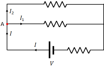
There is a current, $I$ entering the junction A and two other currents, $I_1$ and $I_2$ leaving the junction. Let $q$ be the amount of charge entering the junction $A$ in a time interval $t$. So, the current $I$ is
$I=\dfrac{q}{t}$
The charge, $q$ entering the junction, splits into two: $q_1$ and $q_2$. The charge $q_1$ move to the right and $q_2$ move upwards. Therefore,
$q=q_1+q_2$
The current $I_1$ is due to the flow of charge $q_1$ and $I_2$ is due to the flow of charge, $q_2$.Dividing by $t$, we get
$\dfrac{q}{t}=\dfrac{q_1}{t}+\dfrac{q_2}{t}$
$q_1/t=I_1$ and $q_2/t=I_2$, therefore,
$I=I_1+I_2$
Kirchhoff's current law is also called junction rule.
Kirchhoff's voltage law
Kirchhoff's voltage law is based on the law of conservation of energy. It states that "the sum of the changes in electric potential around any closed loop of a circuit is zero." This law is also called Kirchhoff's loop rule.In a closed electric circuit with a battery, there is an electric potential at any point in the circuit. If you put a charge, q at a point in the circuit, the charge has a potential energy according to the equation,
$PE=q V$
where $V$ is the electric potential at the point.If you move the charge from one point to another, its potential energy changes. If the change in electric potential between the two points is ΔV, then the change in electric potential energy is
$\Delta PE=q\Delta V$
Now, if you take a loop of a circuit, and move the charge across the loop, its potential energy changes as the charge moves from one terminal of an electric element to the other terminal due to the potential difference between the terminals. When the charge makes a round trip, it gains potential energy across some elements and loses potential energy across some other elements. But, if you add the change in electric potential energies, it should be zero for a round trip.
So, if you start a charge at one point and move it around a loop, and bring it back to the starting point, the net change in potential energy of the charge is zero. Since, the change in potential energy of the charge is $q$ times the change in potential, the change in potential across a closed loop is zero.
The following example will help you to understand how to apply the Kirchhoff's voltage law (KVL).
Example: In the following figure, there are three closed loops: ABCF, FCDE and ABDE. Kirchhoff's voltage law is applied over closed loops. Let us apply the voltage law to the loop FCDE.
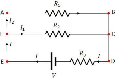
Take a starting point and move across the loop. You can move in the clockwise or in the counter clockwise direction. I take the starting point as F and move in the clockwise direction. First, there is a resistor $R_2$, and $I_1$ is the current through the resistor. You know that, current flows from higher potential to lower potential, so the left terminal of the resistor is at higher potential and the right terminal is at lower potential. Since I move from higher to the lower potential (in the direction of the current), I see a negative change in potential across the resistor. That is, the change in potential across the resistor is $-I_1R_2$. Next, I move across the resistor, $R_3$. Here again, I move in the direction of the current, so the change in potential across the resistor is $-IR_3$. Finally, I move across the battery. Here, I move from the lower potential (negative terminal) to higher potential (positive terminal). So, the change in potential across the battery is $+V$, where $V$ is the voltage of the battery. And I arrives at F, the starting point.
Now, add all the change in electric potentials, which is zero according to the KVL. Therefore,
$-I_1R_2-IR_3+V=0$
Now let us move in the clockwise direction across the same loop and you will get the same equation. I start at the same point F and apply the Kirchhoff's voltage law. I get the following equation,
$-V+IR_3+I_1R_2=0$
The first term is negative as I moved from the higher to lower potential across the battery. The second and the third terms are positive as I moved against the currents across the resistors $R_3$ and $R_2$.
Multiplying this equation with a $-1$, we get
$V-IR_3-I_1R_2=0$
This equation is exactly same as the first equation.Capacitors in electric circuits
Capacitors are important components in electric circuits. In a circuit, capacitors can be connected in series or parallel, like the resistors.
Capacitors in parallel
When capacitors are connected in parallel in a circuit, all the capacitors have same voltage across them, but they have different charges due to the different capacitance values.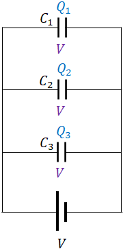
$Q_1=C_1V$; $Q_2=C_2V$ and $Q_3=C_3V$
If $Q$ is the total charge moved by the battery, then
$Q=Q_1+Q_2+Q_3$
Like resistors, we can have a single capacitor that replaces the three capacitors. If $C_{eq}$ is the equivalent capacitance of the equivalent capacitor, then we can write
$C_{eq}=Q/V$
or$C_{eq}=\left(Q_1+Q_2+Q_3\right)/V$
or$C_{eq}=\left(C_1V+C_2V+C_3V\right)/V$
or$C_{eq}=C_1+C_2+C_3$
or$C_{eq}=C_1+C_2+C_3$
i.e., when two or more capacitors are connected in parallel, the equivalent capacitance is the sum of the capacitance of the individual capacitors.Capacitors in series
When capacitors are connected in series, all the capacitors have same charge, $Q$, but have different voltages.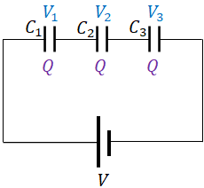
$V_1=\dfrac{Q}{C_1}$; $V_2=\dfrac{Q}{C_2}$; $V_1=\dfrac{Q}{C_3}$.
If $V$ is the battery supply voltage to the circuit, then$V=V_1+V_2+V_3$
If we replace the capacitors with a single equivalent capacitor with capacitance $C_{eq}$, then$C_{eq}=\dfrac{Q}{V}$
or$V=\dfrac{Q}{C_{eq}}$
or$V_1+V_2+V_3=\dfrac{Q}{C_{eq}}$
or$\dfrac{Q}{C_1}+\dfrac{Q}{C_2}+\dfrac{Q}{C_2}=\dfrac{Q}{C_{eq}}$
Dividing out $Q$,$\dfrac{1}{C_1}+\dfrac{1}{C_2}+\dfrac{1}{C_2}=\dfrac{1}{C_{eq}}$
or$\dfrac{1}{C_{eq}}=\dfrac{1}{C_1}+\dfrac{1}{C_2}+\dfrac{1}{C_3}$
i.e., when two or more capacitors are connected in series, the reciprocal of the equivalent capacitance is the sum of the reciprocal of the capacitance of the individual capacitors.RC circuits
An RC circuit is an electric circuit, consists of a resistor and a capacitor connected in series. In the RC circuit, there is also a battery and a switch.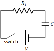
RC circuit- capacitor charging
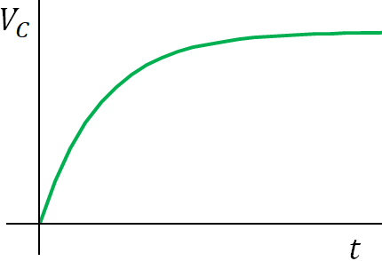
When the switch is closed, the capacitor starts charging and the voltage across the capacitor increases with time:$V_C=V\big(1-e^{-t/\tau})$
where $\tau=RC$ is called the time constant of the circuit, it is a measure of how quickly the capacitor becomes charged. It is also the time required for the capacitor to charge 63 % of the maximum.
$V_R=V-V_C$
Substituting the value for $V_C$, we get$V_R=Ve^{-t/\tau}$
No current can flow through the capacitor, it can only flow to or away from the capacitor. So, the current flows through the circuit is the current through the resistor:$I=\dfrac{V_R}{R}$
$I=\dfrac{V-V_C}{R}$
or$I=\dfrac{V-V\left(1-e^{-t/\tau}\right)}{R}$
or$I=\dfrac{V}{R}e^{-t/\tau}$
Current through an RC-circuit decreases with time exponentially, called exponential decay.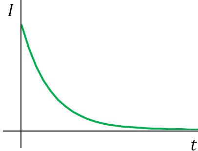
RC circuit- capacitor discharging
Consider the capacitor is fully charged or with some charge $Q_0$. Now, if you remove the battery and close the switch, the capacitor starts discharging as the electrons from the negative plate of the capacitor move to the positive plate. And finally, the two plates will get neutralized.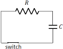
So, the charge across the capacitor decreases with time. The charge, $Q$ across the capacitor after a time $t$ is given by,
$Q=Q_0e^{-t/\tau}$
When the charge decreases, the voltage across the capacitor also decreases proportionally. Therefore, the voltage, $V_C$ across the capacitor is
$V_C=V_0 e^{-t/\tau}$
where $V_0$ is the initial voltage across the capacitor.Ammeters and voltmeters
Ammeters and voltmeters are used to measure current and voltage respectively. When doing measurement, an ammeter should be connected in series in the region, where you want to measure the current. Since voltage is measured between two points in the circuit, a voltmeter should be connected in parallel to the electric components in between the two points.Both the ammeter and the voltmeter use a galvanometer to measure the current or voltage. A galvanometer consists of a coil suspended between the poles of a strong magnet. When a current is applied to the coil, the magnetic force on the coil by the magnet exerts a torque on the coil, and the coil rotates. The rotation angle is proportional to the amount of the current.
The full scale sensitivity of a galvanometer is the amount of current at which the needle of the galvanometer deflects to the full scale. Typical value of full scale sensitivity is 50 µA. This means, the galvanometer cannot measure current if it is greater than 50 µA.
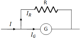
To make a galvanometer to work as an ammeter so that it can measure a wide range of currents, a resistance, called shunt resistance is connected parallel to the galvanometer. The shunt resistance should have a low resistance (much lower than the resistance of the galvanometer) so that most of the current passes through it and a small current passes through the galvanometer.
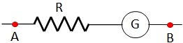
To use a galvanometer as a voltmeter, a larger resistance (much larger than the resistance of the galvanometer) should be connected in series to the galvanometer. So, there is more voltage drop across the resistor and less voltage across the galvanometer, which results in less current through it. The points A and B of the following circuit (the voltmeter) is connected to the desired points of the circuit, between which the voltage is being measured.